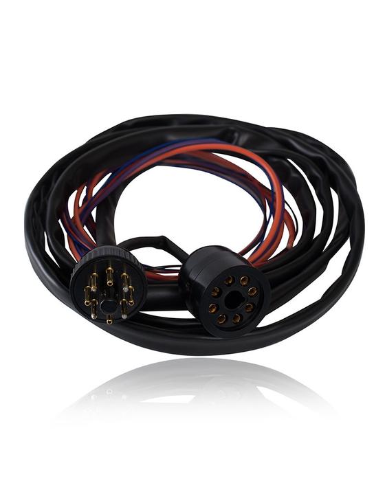
Photron's P205-SensAA is designed for use in our P200 Superlamp powersupply for GBC's SensAA AAS instruments.
Designed for P800S 3volt superlamps
Installation Instructions
Objective: To connect a Photron Super lamp Power Supply to a GBC SensAA.
Materials:
- GBC SensAA AAS
- Photron 3 volt super lamp power supply P200
- Photron P205-SensAA adapter kit
Procedures: Warning: When powered, lamp circuitry runs at high voltage.
- Turn off power to instrument and unplug.
- Remove cover from AA.
- Unscrew the rear octal cover from lamp socket.
- Note the 2 black wires soldered to pins 1 and 3 of the octal socket.
- With tape or similar, mark each black wire with its pin numbers 1 and 3.
- Unsolder each black wire from the octal socket.
- Note the 2 black wires soldered to pins 5 and 7 of the octal socket.
- With tape or similar, mark each black wire with its pin numbers 5 and 7.
- Unsolder each black wire from the octal socket.
- Solder black wire ‰ÛÏ1‰ to the black wire on adapter.
- Solder black wire ‰ÛÏ3‰ to the red wire on adapter.
- Solder black wire ‰ÛÏ5‰ to the brown wire on adapter.
- Solder black wire ‰ÛÏ7‰ to the light blue wire on adapter.
- Insulate both of these connections with 2 layers of heat shrink tubing.
- Solder the white wire on the adapter to pin 3 of the octal socket.
- Solder the blue wire on the adapter to pin 1 of the octal socket.
- Solder the violet wire on the adapter to pin 7 of the octal socket.
- Solder the orange wire on the adapter to pin 5 of the octal socket. It is best to cut the wire so they are only as long as they need to be to minimize filament current voltage drops.
- Connect octal plug P1 to octal socket on flying lead from Superlamp Power Supply.
- Connect octal socket S1 to octal plug mounted on rear of Superlamp Power Supply
- Remove top cover of Photron Superlamp Power Supply.
- Locate trimpot on the smaller filament control PCB.
- Connect multimeter leads to pins 5 and 7 of lamp socket with a superlamp plugged in.
- Adjust trimpot until voltage equals 2.4 Volts DC.
- Replace covers
- The switch should only be changed in position when the instrument is turned off.
Lamp position 1 will only operate as a Superlamp.

